

What are the signs of the valves?
Industrial valve logo, paint, supply, the state and various industrial departments have formulated a unified standard, is the basis of supply and receiving between suppliers and users. Type, structure of the valve, the size, material, nominal size (diameter), or nominal pressure (or working pressure), the applicable medium, temperature and closing direction.
What is the sign of a valve?
The content of the logo
The ns that must be used for general valves and items that can be used are shown in Table 1-1.
Table 1-1 Sign of the valve
| project | logo | project | logo |
| 1 | Nominal size(DN) | 11 | Standard |
| 2 | Nominal pressure (PN) | 12 | Smelting furnace number |
| 3 | Pressure parts material code | 13 | Internal parts material code |
| 4 | Manufacturer's name or trademark | 14 | Workstation number |
| 5 | media flow arrow | 15 | Lining material code |
| 6 | Seal ring (gasket) code | 16 | Quality and test marks |
| 7 | Limit temperature(℃) | 17 | Inspector's mark |
| 8 | Thread code | 18 | Manufacturing year and month |
| 9 | ultimate pressure | 19 | Flow characteristics |
| 10 | Factory number |
Note: The nominal pressure casting mark on the valve body is equal to 10 times the number of mempa (MPa). When set at the nominal size value, it is not labeled by PN.
The outer surface of the valve pressure valve body should be marked with permanent marks according to the provisions, the logo should have the nominal size (DN), nominal pressure (PN), shell material name or trademark, furnace number (casting valve), the flow direction of the valve marked medium direction arrow.
There are other regulations for some high temperature, high pressure and corrosion resistant valves and special use valves that can be marked on the valve body or sign when required.
Valves have the marking of the marking method?
① The valve body is formed by casting or die casting method, and its mark is cast at the same time with the valve body.
② When the shape of the valve body is formed by the die forging method, its mark in addition to the die forging or die casting with the valve body, can also be used forging processing, steel pipe or steel plate coil welding forming, its mark in addition to the method of stamping, can also use other methods that do not affect the performance of the valve body (such as laser printing method).
The marking pattern of the valve marks?
The nominal dimension value mark, pressure code, or working pressure code, and flow direction mark shall be above the pressure code in accordance with the combined style specified in Table 1-2.
Table 1-2, along with the marker pattern
| valve body | media flow | Nominal ruler | Nominal ruler | inch unit |
| form | moving direction | Cunhe Gong | inch and work | Diameter and scale |
| weighing pressure | work pressure | |||
| Straight-through | The medium consists of a | DN50 | DN50 | 2 |
| Or angle form | Import direction | → | → | → |
| One flow to another | 16 | P54140 | 150 | |
| an exit | ||||
| tee type | The medium consists of a | DN100 | — | |
| Import to two | 16 | |||
| export flows | 300 | |||
| (Three-way diversion) | ||||
| The medium consists of two | DN150 | — | ||
| 600 |
Note: 1. Valves whose media can flow from either direction are not marked with arrows.
- Below the arrow in the formula is the nominal pressure code, and the value is 10 times of the nominal pressure value (in MPa).
- The style is inch units, the top indicates the valve diameter (unit: in), and the bottom indicates the pound pressure (unit: lb).
Where is the marking position of the valve sign?
① Mark content, generally marked in the valve body easy to watch parts. The mark shall be marked in the lumen position of the vertical centerline of the body.
② When the mark content is not enough marked on one surface of the valve body, it can be marked on the other side of the cavity symmetry position in the valve body.
③ The ns should be obvious, clear, orderly and symmetrical.
Valve marker size
① The size of casting marks, the arrangement of fonts and arrows as in Figure 1-1, the size of fonts and arrows shall be specified in Table 1-3, and the protruding section shall be made.
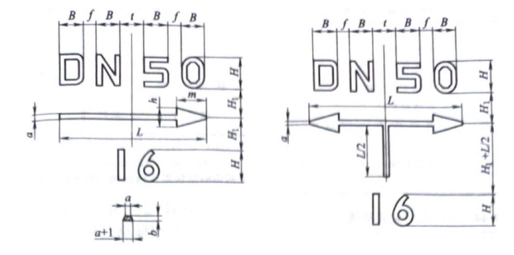 Figure 1-1 Casting of mark dimensions
Table 1-3 Size of casting markUnit: mm
| Font number | arrowhead | bisect | ||||||||
| H | H₁ | h | B | f | t | m | L | a | B | |
| 7 | 7 | 5 | 5 | 3 | 5 | 7 | 30 | 1.5 | 2 | |
| 10 | 10 | 7 | 5 | 7 | 6 | 9 | 40 | |||
| 14 | 14 | 10 | 7 | 10 | 5 | 10 | 12 | 65 | 2 | 2 |
| 20 | 20 | 14 | 10 | 14 | 7 | 14 | 16 | 90 | ||
| 26 | 26 | 16 | 13 | 20 | 10 | 16 | 20 | 120 | 3 | 3 |
| 32 | 32 | 18 | 16 | 24 | 12 | 18 | 25 | 150 | ||
| 40 | 40 | 22 | 20 | 30 | 15 | 22 | 35 | 150 | ||
| 48 | 48 | 27 | 24 | 36 | 18 | 25 | 42 | 210 | 4 | 4 |
| 60 | 60 | 34 | 30 | 45 | 22 | 32 | 52 | 260 | 5 | 5 |
② Press and print the mark size as specified in Table 1-4. Arrow dimensions are specified by the design drawings.
Table 1-4 Size of imprint marks Unit: mm
| Font number | 3.5 | 5 | 7 | 10 | 14 | |
| digital sum letters of an alphabet | altitude | 3.5 | 5 | 7 | 10 | 14 |
| Width (except for M, W letters) | 2.5 | 3.5 | 5 | 7 | 10 | |
| word space | 1.5 | 2 | 2 | 3 | 5 | |
| Width of the letter (M, W) | 3.5 | 5 | 7 | 10 | 14 | |
| The depth of the press | ≥0.5 | |||||
③ The font number of each product logo can be selected according to Table 1-5, or it can also be specified by the design drawing according to the specific shape and size of the product.
Table 1-5 Font No. Unit: mm
| intended size | ≥10 | 15~25 | 32~50 | 65~100 | 125~200 | 250~300 | 350~450 | 500~700 | 800~1000 | ≥1200 | |
| Font number | cast-on outwell | — | 7 | 10 | 14 | 20 | 26 | 32 | 40 | 48 | 60 |
| stamp | 3 .5 Or 5 | 7 | 10 | 14 | |||||||
How to know the sign of the valve?
The sign is usually fixed on the valve body, flange or hand wheel, and the data of the sign is relatively complete, reflecting the basic characteristics of the valve. Different valves give different signs (Table 1-6~ Table 1-11).
Table 1-6 Metal nameplate of stop, check, gate, throttle, stopcock and diaphragm valves
| product name: | product number, |
| Product number: | Applicable media: |
| Nominal pressure PN: | Seal ring (gasket) code: (select) |
| Nominal size DN: | Lining material code: (select) |
| Working temperature t/℃: | Flow coefficient/(mm²/h): (select) |
| Shell material grade: | Opening torque/N·m: (select) |
| Manufacturing date: year month day | Manufacturing unit: |
Table 1-7 Metal nameplate of the regulating valve
| product name: | Product number: |
| Product number: | Flow coefficient C: |
| Applicable media: | Working pressure p/MPa: |
| Nominal pressure PN: | Maximum operating temperature t/℃: |
| Nominal size D N: | Shell material: |
| Inlet pressure p₁/(temperature h)/MPa(℃): | Outlet pressure p z / (temperature t z ) /MPa(℃): |
| Maximum pressure difference △p/MPa: | Manufacturing date: year month day |
| Manufacturing unit: |
Table 1-8 Metal nameplate of the safety valve
| product name: | Product number: |
| Product number: | Shell material: (marked on the valve body and can be omitted) |
| Applicable media, | Emission coefficient C: (select) |
| Flow channel diameter (valve diameter) D₁/mm: | Valve disc opening height H/mm: |
| Working pressure p/MPa: | Back pressure/MPa: (select) |
| Set pressure/MPa: | Maximum operating temperature t/℃: |
| Manufacturing unit: | Manufacturing date: year month day |
Table 1-9 Metal nameplate of the pressure reducing valve
| product name: | Product number: |
| Product number: | Shell material: |
| Applicable media: | Nominal size DN: |
| Nominal pressure PN: | Maximum operating temperature t/℃: |
| Inlet pressure p₁ (temperature t₁)/MPa(℃): | Outlet pressure p z (temperature t z )MPa (℃): |
| Manufacturing unit: | Manufacturing date: year month day |
Table 1-10 Metal nameplate of the temperature reducing and pressure reducing valve
| product name: | product number; |
| Product number: | Rated flow coefficient C/(t/h or m³/h): |
| Applicable media: | Working pressure p/MPa: |
| Nominal pressure PN: | Outlet pressure p z / (temperature t z ) /MPa(℃): |
| Inlet pressure p₁ (temperature t₁)/MPa(℃): | Nominal size of outlet DN₂: |
| Imported nominal size DN₁/mm: | Shell material: |
| Maximum pressure difference △p/MPa; | Manufacturing date: year month day |
| Manufacturing unit: |
Table 1-11 Metal nameplates of the steam traps
| product name: | Shell material: |
| Product number: | Maximum allowable pressure/MPa: (select) |
| Nominal pressure PN: | Maximum allowable temperature Tmi/℃: (select) |
| Nominal size DN: | Maximum drainage temperature Tm/℃: (select) |
| Maximum working pressure p/MPa; | Maximum displacement/(kg/h): (select) |
| Maximum operating temperature t/℃: | Manufacturing unit (trademark): |
| Manufacturing date: year month day |