English
 Español

How to Measure a Butterfly Valve Correctly: From Face-to-Face to Bolt Circle
Specifying the wrong butterfly valve size is one of the most expensive mistakes your procurement or engineering team can make. A valve that does not match the pipeline's face-to-face length, bolt circle, or flange standard will not seat correctly, can leak under pressure, and usually means a costly re-order plus unplanned downtime for your plant.
In this guide, we walk you through exactly how to measure a butterfly valve size using the same field method our FLOWORK engineers apply before every shipment. You will learn the critical butterfly valve dimensions you must capture, a step-by-step measuring process, the international standards that govern them, and a practical size chart in millimeters you can trust on your next site visit. By the end, you will be able to confirm a replacement or a new specification with confidence—and avoid the common measuring errors that quietly delay B2B projects.
Why Accurate Butterfly Valve Dimensions Matter for Your Project
When you order a butterfly valve for a retrofit or a new line, the drawing on the PDF is only half the story. What actually determines whether the valve fits is a handful of physical dimensions: the face-to-face length, the bolt circle diameter, the number and size of bolt holes, and the overall height that must clear your actuator and piping. If any of these are off by even a few millimeters, the flange will not line up, the bolts will not pass through, and your installation crew is left grinding, shimming, or sending the valve back. For your business, that translates directly into delayed commissioning, demurrage on international shipments, and strained relationships with the end client.
There is also a compliance angle that procurement teams cannot ignore. Most industrial projects in oil and gas, petrochemical, marine, and thermal power require valves built to recognized standards such as API 609, API 607, API 598, and ISO 9001, with CE marking for the European market. At FLOWORK, every butterfly valve is designed, machined, and pressure-tested against these benchmarks before it leaves the factory, so the dimensions you measure on site should match the certified drawing exactly. Treating measurement as a checkbox instead of a discipline is how mismatches slip through—so let us start with the dimensions themselves.
Key Butterfly Valve Dimensions You Need to Know
Before you pick up a tape measure, it helps to speak the same language as the butterfly valve drawing your supplier sends. The five dimensions below are the ones that decide fit and interchangeability, and they are exactly what you will record in Section 4.
Overall Length (Face-to-Face Dimension)
The butterfly valve face to face dimensions—sometimes written as F2F or FTF—is the distance between the two sealing faces of the valve where it meets the pipeline flanges. This is the single most important number on the order, because it defines how much space the valve occupies between flanges. Butterfly valves are compact by design, but the exact face-to-face length still changes with nominal size, pressure class, and whether the valve follows a short or long pattern. Always measure this with the valve fully closed and laid on a flat surface, from one flange contact face to the other.
Outside Diameter (OD) and Disc Diameter
The outside diameter usually refers to the rim of the valve body or the lug/wafer outline, while the disc diameter is the size of the rotating closure member inside. You will not always need the disc diameter to confirm a fit, but it matters when you are checking flow capacity or verifying that a replacement disc matches the seat. In practice, most buyers only need the body outside diameter to confirm clearance inside a tight valve pit or skid, so record it only if space is constrained.
Bolt Circle Diameter (BCD) and Bolt Hole Pattern
The butterfly valve bolt circle diameter is the invisible circle that passes through the center of every bolt hole, and the bolt hole pattern is the count, diameter, and arrangement of those holes. Together they decide whether your valve's bolts will line up with the companion flange. A common error is measuring the outside of the flange instead of the bolt circle; the BCD is almost always smaller than the flange OD. Get this wrong and no amount of force will pull the joint together.

Body Width and Overall Height
Body width is the thickness of the valve across the pipeline axis (essentially the face-to-face for a wafer or lug body), and overall height includes the actuator pad, gearbox, or handle on top. Overall height is the dimension that surprises people during retrofits: a valve that fits perfectly between flanges may still foul a walkway, cable tray, or adjacent pipe because the actuator is taller than the old one. Always check the installed height envelope before you commit the order, especially for automated FLOWORK butterfly valves with pneumatic or electric actuators.
How to Measure Butterfly Valve Size Step by Step
The good news is that you do not need a metrology lab to learn how to measure butterfly valve size correctly. With a few basic tools and a clear sequence, you can capture every dimension your supplier needs to ship a matching valve. Work through the four steps below in order, and write each value down as you go.
Tools You'll Need
Start with a steel measuring tape (fabric tapes stretch and lie), a vernier or digital caliper for small bolt holes, a straight edge or ruler for flat reference, and a notepad or phone to record values. For installed valves, a set of inside calipers or a bore gauge helps you reach dimensions you cannot see directly. If your project demands certified numbers, a laser meter or a factory inspection report from the original supplier is the safest source—field measurement is great for verification, but the certified drawing is what the shop builds to.

Step 1 — Measure the Pipe Nominal Diameter
First, confirm the nominal diameter of the line, not the valve. Measure the inside diameter of the companion pipe with your caliper or bore gauge, then convert it to the nearest DN (metric) or NPS (inch) nominal size using the standard conversion tables. Do not guess from the outside of the pipe, because wall thickness varies by schedule. Recording the correct DN/NPS up front prevents the classic mistake of ordering a DN150 valve for a DN125 line just because the flanges looked similar.
Step 2 — Measure Face-to-Face Length
Lay the valve on a flat, clean surface and measure from the sealing face on one side to the sealing face on the other. Use the straight edge to ensure the tape is square to the body, and take the reading at the extreme contact points, not the corners of the lug ears. Compare your measured face-to-face against the chart in Section 6; if it matches a short-pattern API 609 value, you can use a wafer or lug style, but if it matches a long-pattern or double-flanged value, you will need a different body design.
Step 3 — Measure Bolt Circle and Bolt Holes
This is the step that shows how to measure bolt circle values that actually line up in the field. To find the bolt circle diameter, measure the distance between the centers of two opposite bolt holes and add the bolt hole diameter—or simply measure center-to-center across the diameter and record that span. Count the bolt holes, measure one hole's diameter with the caliper, and note whether the holes are threaded (lug) or plain (wafer). Small errors here are the number-one cause of flanges that will not bolt up, so a digital caliper earns its keep at this stage.
Step 4 — Confirm Wafer, Lug, or Flanged Type
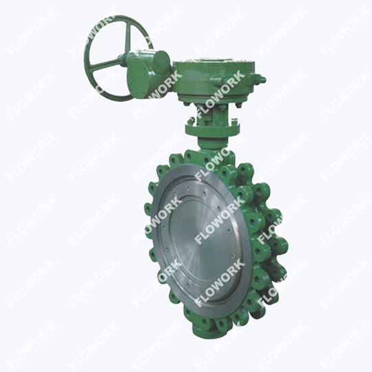
Finally, confirm the mounting type, because it changes both the dimensions and what you can do with the valve later. A wafer butterfly valve is sandwiched between two flanges and held by through-bolts; a lug type has threaded inserts so it can be bolted at one end even when the other flange is removed; a flanged (double-flanged) type has its own mating flanges and is used where you need a rigid, bolted joint. Each style shares the same bore but differs in body width and bolt-hole design, so tell your supplier which one you measured. You can review the full range of wafer, lug, and flanged butterfly valves we manufacture before you finalize the specification.
Need a Dimension Sheet You Can Hand to Your Procurement Team?
Send us your measured values and our engineers will confirm the exact model and price for your line.
Butterfly Valve Dimensions Standard (ASME, DIN, ISO/EN Compared)
You will often hear dimensions quoted "to ASME" or "to DIN," and the difference is not cosmetic—it changes the actual face-to-face length and bolt circle your valve must meet. Understanding which standard governs your project prevents you from mixing an EN-558 valve into an ASME line. The comparison below covers the four standards most B2B buyers meet, and you can read our deeper breakdown of valve design and manufacturing standards in our technical resource library.
ASME B16.10 / MSS SP-67 (Inch/US Standard)
In North America, face-to-face lengths for an ASME B16.10 butterfly valve body are governed by ASME B16.10, while MSS SP-67 covers the general requirements for butterfly valves including the short (wafer/lug) pattern. Values are quoted in inches, and the butterfly valve flange dimensions (bolt circle and hole pattern) follow ASME B16.5 for Class 150, 300, and higher ratings. If your project is engineered in the US or follows ANSI piping, this is the table your supplier will build to, and the millimeter chart in Section 6 is simply the converted equivalent.
DIN / EN 558 (Metric Standard)
In Europe and most of Asia, DIN EN 558 butterfly valve dimensions follow EN 558 (the successor to DIN 3202), which defines series such as Series 20 for short-pattern butterfly valves. Everything is in millimeters, and the flange drillings follow EN 1092-1. The practical takeaway for your business is that a DN300 valve built to EN 558 Series 20 will bolt into a metric flange set even if the companion equipment came from a different European maker—provided both sides honor the same series.
| Standard | Region | Reference Basis | Typical Unit |
|---|---|---|---|
| ASME B16.10 / MSS SP-67 | North America (US) | Face-to-face lengths for valves; short pattern per API 609 | Inches (mm equivalents) |
| EN 558 (formerly DIN 3202) | Europe | Face-to-face series for butterfly valves (e.g., Series 20) | Millimeters |
| ISO 5752 | International | Face-to-face for butterfly valves, short & long pattern | Millimeters |
| API 609 | International (US-origin) | Butterfly valve design, materials & dimensions | Inches / mm |
| JIS B2002 | Japan | Face-to-face dimensions | Millimeters / inches |
Butterfly Valve Dimensions in mm: Size Chart by Nominal Diameter
The chart below gives typical butterfly valve dimensions in mm for ANSI Class 150 wafer and lug butterfly valves, the pattern most common in international B2B projects. Use it as a quick field check: if your measured face-to-face and bolt circle sit close to these numbers, you are almost certainly holding a Class 150 short-pattern valve. Always confirm the exact values against the certified drawing for your specific model, because face-to-face can shift between short and long patterns and between pressure classes.
| DN (mm) | NPS (inch) | Face-to-Face (mm) | Bolt Circle (mm) | Bolt Holes | Approx. Weight (kg) |
|---|---|---|---|---|---|
| DN50 | NPS 2" | 43 | 120.7 | 4 × ø16 | 3 |
| DN80 | NPS 3" | 46 | 152.4 | 4 × ø16 | 5 |
| DN100 | NPS 4" | 52 | 190.5 | 8 × ø16 | 7 |
| DN150 | NPS 6" | 56 | 241.3 | 8 × ø20 | 11 |
| DN200 | NPS 8" | 64 | 298.5 | 8 × ø20 | 17 |
| DN250 | NPS 10" | 71 | 362.0 | 12 × ø22 | 26 |
| DN300 | NPS 12" | 81 | 432.0 | 12 × ø22 | 38 |
| DN350 | NPS 14" | 92 | 476.3 | 12 × ø22 | 55 |
| DN400 | NPS 16" | 111 | 539.8 | 16 × ø22 | 75 |
| DN500 | NPS 20" | 130 | 635.0 | 20 × ø22 | 120 |
| DN600 | NPS 24" | 162 | 749.3 | 20 × ø25 | 190 |
Typical values for ANSI Class 150 wafer/lug butterfly valves (short pattern, API 609). Face-to-face and bolt circle vary by pressure class and manufacturer; confirm against the certified FLOWORK drawing before ordering.
Butterfly Valve Size Chart: Matching Size to Your Application
Dimensions tell you what fits; application tells you what to specify. The same nominal size behaves very differently in an HVAC chiller room versus a crude unit in a refinery, so use the size bands below as a starting point and let flow, pressure, and media decide the final butterfly valve specifications. You can explore our full butterfly valve range to match body material and actuator to the duty.

Small Sizes (DN50–DN200) for HVAC and Water Systems
Small butterfly valves are the workhorses of commercial HVAC, cooling water, irrigation, and building services. At DN50 to DN200 they are light enough to install by hand, cheap to automate with a compact electric actuator, and tight enough to hold off air-conditioning chiller pressures. For your business, this is where standard wafer bodies with EPDM or NBR seats usually do the job, and where lead times are shortest because they are stock items for most suppliers.
Mid-to-Large Sizes (DN250–DN600) for Industrial Pipelines
The DN250 to DN600 band covers the bulk of process and utility piping in factories, power stations, and water treatment plants. Here you start to care about body material—carbon steel for general service, stainless steel for corrosive or hygienic duty—and about the actuator torque, because a DN600 disc sees real hydrostatic force. Lug and flanged styles become common when you need to break the line at the valve without dropping the whole spool, which matters for maintenance access in continuous-process plants.
Large Sizes (DN700+) for Oil, Gas, and Power Plants
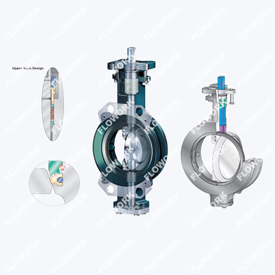
Above DN700, butterfly valves move into critical service: seawater intake, cooling circuits in thermal power, and isolation in oil and gas gathering lines. At this scale, face-to-face and bolt circle must be exact because the valve is lifted by crane and aligned to millimeter tolerances, and a mismatch can halt a turnaround. Double-offset and triple-offset designs appear here for bubble-tight shutoff and fire-safe performance, and every dimension is verified against the project's approved datasheet before shipment.
Specifying DN250 or Larger? Let Our Engineers Size It With You
Send your line size, pressure, temperature, and media, and we will return a matched model with certified dimensions and a quote.
Common Mistakes to Avoid When Measuring Butterfly Valve Size
Most fit problems trace back to a short list of repeating errors. These butterfly valve installation measurements must be exact, so avoid the mistakes below and your replacement valve will seat on the first try.
- Measuring the flange OD instead of the bolt circle. The BCD is the circle through the bolt-hole centers, not the outer edge of the flange—always measure center-to-center across the diameter.
- Confusing short and long pattern. A wafer valve and a double-flanged valve of the same DN can have very different face-to-face lengths; match the pattern, not just the bore.
- Guessing DN from pipe outside diameter. Wall thickness varies by schedule, so measure the bore or read the stamping on the flange.
- Forgetting the actuator envelope. The valve may fit between flanges but foul a walkway or cable tray because the gearbox is taller than the old one.
- Mixing standards. An EN 558 valve will not always drop into an ASME B16.10 line even at the same DN—confirm the governing standard on the project spec.
- Relying on a fabric tape. Cloth tapes stretch; use a steel tape or caliper for dimensions that must be accurate to the millimeter.
FAQs
How do I know if I need a wafer, lug, or flanged butterfly valve?
It depends on how you install and maintain the line. Choose a wafer type when the valve is sandwiched between two flanges and held by through-bolts—the most common and lowest-cost option. Choose a lug type when you must bolt it at one end with the other flange removed, or when dead-end service is possible. Choose a flanged (double-flanged) type for rigid, bolted joints in critical or high-vibration service. Your measured bolt-hole pattern and body width will confirm which one you already have.
What is the difference between face-to-face and center-to-face dimensions?
Face-to-face (F2F) is the distance between the two sealing faces of the valve body and is what you measure for a wafer or lug valve. Center-to-face (C2F) is measured from the pipeline centerline to one flange face and is used for some gate and globe valves. For butterfly valves you almost always work in face-to-face; if a supplier quotes center-to-face, ask for the face-to-face equivalent so your flange gap matches.
Can I replace an existing butterfly valve with a different brand using the same measurements?
Usually yes, provided the DN/NPS, face-to-face pattern (short vs long), bolt circle, bolt-hole count and size, and pressure class all match. Interchangeability is exactly why standards like API 609 and EN 558 exist. The risk is in the details: when you measure butterfly valve for replacement, disc thickness, seat type, and actuator mounting can differ between brands, so always send your measured dimensions and the old nameplate photo to the new supplier for confirmation before ordering.
How do I measure the bolt circle diameter if the valve is already installed?
With the valve in place, measure the center-to-center distance between two opposite bolt holes across the flange, then add one bolt-hole diameter to reach the bolt circle. If the bolts are in the way, measure from the outside edge of one hole to the inside edge of the opposite hole and add the hole diameter. A caliper or inside micrometer gives the most reliable reading when access is tight.
Do butterfly valve dimensions change between ANSI Class 150, 300, and higher?
Yes. Face-to-face length stays similar for short-pattern wafer/lug valves across many classes, but the bolt circle diameter, bolt-hole size, and count grow as the pressure class rises because the flange must carry more load. Always state the pressure class when you request dimensions; a Class 300 valve will not bolt into a Class 150 flange even at the same DN.
Which standards should my butterfly valve comply with for oil & gas or petrochemical projects?
For international oil, gas, and petrochemical service, specify valves to API 609 for design, API 607 for fire safety, API 598 for testing, and ISO 9001 for quality management, with CE marking where the European market requires it.
How do I convert DN to NPS when ordering a butterfly valve?
DN is the metric nominal size in millimeters and NPS is the inch-based nominal size; they are paired but not equal in value (for example DN150 ≈ NPS 6"). Use a standard DN-to-NPS table, or the chart in Section 6, to pick the matching pair, and always state both on the purchase order so there is no ambiguity between a metric and an inch-based flange set.
Conclusion
Measuring a butterfly valve correctly is not complicated, but it is unforgiving: a few millimeters on the face-to-face or bolt circle decide whether your valve ships, seats, and holds pressure or comes back as a costly mistake. Walk the four steps in this butterfly valve sizing guide—confirm the nominal diameter, measure the face-to-face, capture the bolt circle and holes, and verify the wafer, lug, or flanged type—and check every value against the standards and charts above. When the numbers match, your business avoids downtime, keeps the project on schedule, and builds a spec your supplier can execute first time.
Browse the FLOWORK butterfly valve catalogue to see the body materials, actuators, and pressure classes we offer, or reach out and we will size the valve with you.
Ready to Confirm Your Butterfly Valve Size?
Send us your measured face-to-face, bolt circle, and DN/NPS, and FLOWORK will match the exact model. Trusted by oil & gas, petrochemical, marine, and power clients worldwide.