Putting a new valve into a piping system looks simple on paper, but field mistakes can destroy your equipment in days. Proper globe valve installation decides whether your processing line runs smoothly or stops for emergency repairs. This practical guide covers essential orientation rules, flow direction choices, and troubleshooting steps to safeguard your factory uptime.
What Is a Globe Valve
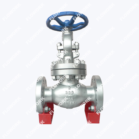
A globe valve is a heavy-duty industrial device used to change, slow down, or completely stop the movement of liquids and gases through a pipe. Unlike ball valves that swing open quickly, this valve moves a round disc straight up and down like a piston inside a car engine.
What Are Industrial Globe Valves Used For
Precision Throttling: They are the absolute best choice when you need to adjust flow rates to precise percentages rather than just turning a line fully on or off.
Bypass Control Lines: Factories install them alongside automated control valves so workers can manually regulate pressure during system maintenance.
High-Pressure Isolation: They handle severe pressure drops in cooling water loops, chemical processing networks, and oil refining lines without shaking apart.
Core Globe Valve Characteristics and Mechanical Advantages
Short Travel Distance: Because the plug only needs to lift a short distance away from the seat ring to fully open, operators can open and close them much faster than gate valves.
Easy Seat Refurbishment: You can easily lap or grind the internal seating surfaces right inside the pipeline without cutting the entire valve body out of the system.
Linear Flow Matching: The physical space between the disc and the seat increases proportionally as you turn the handwheel, making flow adjustments predictable.
Globe Valve Standard: API 623 vs. BS 1868
When your business procures heavy-duty throttling hardware, understanding the governing design standards prevents premature field failures. Industrial globe valves are generally designed around two major international frameworks: API 623 (American Petroleum Institute) and BS 1868 (British Standard).
API 623 (The Modern Refinery Standard): Introduced to address the shortcomings of older designs in high-pressure, high-vibration petroleum environments. It mandates fully guided discs to stop seat chattering and enforces thicker stem diameters to prevent buckling under high actuation loads.
BS 1868 (The Traditional British Framework): While globally respected for general industrial and power piping loops, BS 1868 allows for more flexible, lighter-weight wall thicknesses. However, for severe shifting pressures or continuous throttling, upgrading to an API 623 heavy-wall construction protects your facility from premature seat deformation.
Why Is Correct Globe Valve Flow Direction Vital for Pipeline Safety
Every industrial globe valve has a raised metal arrow stamped onto the outside of its body. This is your guide for globe valve flow direction. If you ignore this arrow during a globe valve installation, you risk damaging the valve internals, ruining your system pressure balance, or injuring your maintenance staff.
Flow Under the Disc: Low Operating Torque and Packing Protection
Pressure Relief on Sealing: When fluid enters beneath the valve disc, the system pressure pushes upward against the bottom of the plug. When the valve is closed, there is zero line pressure hitting the stem packing.
Safe Maintenance Clearances: Because the packing area is isolated from the main pressure loop when closed, technicians can safely adjust or swap out the sealing braids without dangerous fluid leaks.
Easier Emergency Opening: The fluid pressure actually helps lift the disc up when you turn the handwheel, meaning your workers or automated actuators need far less physical force to crack the valve open.
Flow Over the Disc: High-Pressure Steam Separation and Leak Prevention
Combating Thermal Contraction: In superheated steam lines, valves cool down when shut off, causing metal stems to shrink slightly. Flow entering from the top pushes down on the disc, keeping it tightly sealed despite metal contraction.
Preventing Internal Bypassing: High pressure acts like a continuous clamp, pressing the disc directly into the seat ring to ensure a tight seal over long shutdown periods.
Specialized Execution: This setup is common in boiler feedwater systems and high-pressure steam isolation loops where a small internal leak could erode the metal seat within weeks.
What Are the Consequences of Installing a Globe Valve Backwards
Stem Thread Stripping: Forcing a valve open against high pressure hitting the top of the disc can strip the internal stem threads, leaving the valve permanently stuck shut.
Violent Seat Chattering: Fluid hitting a reverse-installed disc creates massive turbulence, causing the plug to slam repeatedly against the seat ring, which destroys the polished metal faces.
Extreme Packing Blown-outs: Keeping high pressure constantly pressed against the soft stem packing causes rapid chemical weeping, hazardous air emissions, and eventual total seal blowout.
How to Choose the Right Globe Valve Installation Orientation
Where and how you position the valve stem in three-dimensional space determines how long the soft seals inside will survive. Good piping geometry stops gravity from turning your process media into a destructive force against your equipment.
Horizontal Pipe Runs with Upright Stem Alignment
The Industry Golden Rule: Always try to position your globe valve assembly on a straight horizontal pipe run with the heavy handwheel pointing straight up toward the ceiling.
Gravity Deflection Control: Keeping the stem perfectly vertical stops the heavy internal disc assembly from sagging to one side, ensuring the plug drops perfectly straight into the center of the seat ring.
Even Wear Spreading: This positioning spreads friction evenly across the low friction bearings and internal guide walls, stopping one-sided gouges that cause jamming.
Globe Valve Vertical Installation Limits: Upward vs. Downward Flow Realities
Upward Flow Mandate: A globe valve vertical installation works perfectly fine, but only if the process liquid or gas is moving upward against gravity.
Avoiding Downward Fluid Slams: Never mount a globe valve on a vertical drop where fluid travels downward; gravity combined with fluid weight creates massive pressure spikes and severe water hammer when closing.
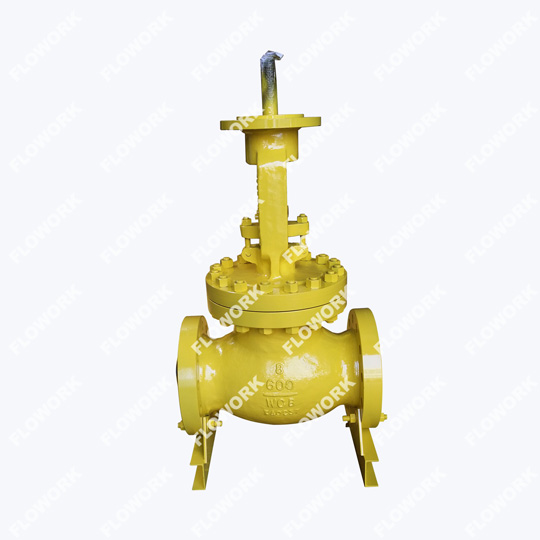
Actuator Weight Support: If you put a heavy pneumatic actuator on a vertically mounted valve, you must build external structural steel supports to stop the pipe from bending under the weight.
Why Upside-Down Stem Mounting Causes Total Packing Failure
Debris Trapping Cavities: Mounting a valve upside down turns the bonnet area into a low-point collection bucket for pipe scale, welding slag, and corrosive rust particles.
Abrasive Stem Scoring: Every time you turn the handwheel, those trapped metal flakes grind against the smooth stem and soft packing rings, carving deep grooves that allow fluid to escape.
Actuator Drenching Hazards: If the packing leaks on an inverted valve, hazardous chemicals or boiling liquids will drip straight down onto expensive electric motors or positioners, causing electrical shorts.
Globe Valve Installation: A Step-by-Step Engineering Guide
Follow this standard procedure to ensure your valve seats perfectly, holds pressure, and operates smoothly from day one.
Pre-Installation Pipeline Flushing and Flange Alignment Checks
Blast Out Pipeline Trash: Run high-speed water or air through the open pipe lines before dropping the valve into place to wash away loose sand, rust particles, and old welding slag.
Check Face Parallelism: Use a level to ensure the matching pipe flanges are perfectly square and parallel; forcing a valve into place using flange bolts bends the valve body and binds the internal stem.
Inspect Internal Seating: Peer inside the valve ports to verify that no plastic packing peanuts or cardboard dust caps are trapped near the plug assembly before tightening the joints.
Welding Procedures for a Socket Weld Globe Valve Assembly
Crack the Disc Open: When installing a socket weld globe valve, you must turn the handwheel to lift the disc roughly 10% to 15% off the seat before firing up your welding torch.
Preventing Seat Fusion: Leaving the valve fully closed during welding causes the expanding metal seat ring to warp or fuse permanently to the soft body gaskets under intense heat.
Use Heat Sink Wraps: Wrap damp rag barriers around the main center bonnet flange to pull heat away from the critical sealing area while welding the pipe sockets.
Bolt Torque Sequencing and Controlled Gasket Seating
Lubricate Fastener Threads: Apply a light layer of high-temperature anti-seize compound to all bolt threads to guarantee smooth torque delivery during assembly.
Follow the Star Pattern: Tighten the flange bolts in a star cross-pattern using incremental torque stages (30%, 60%, 100%) to apply completely even pressure across the gasket face.
Verify Stem Freedom: Turn the handwheel fully open and fully closed after final torque application to confirm that no body warping has locked up the internal drive mechanism.
How Does Cryogenic Globe Valve Installation Differ from a Standard Globe Valve
Super-cold fluids like liquid nitrogen, LNG, or liquid carbon dioxide require specialized installation choices. Standard utility valves will freeze solid and snap under these extreme thermal shocks. To guarantee absolute safety, field engineering must align with key industry benchmarks like the British Standard BS 6364 and the ultra-strict SHELL MESC SPE 77/200 specification.
Extended Bonnet Orientation Angle Limits for Liquid Hydrogen/LNG Service
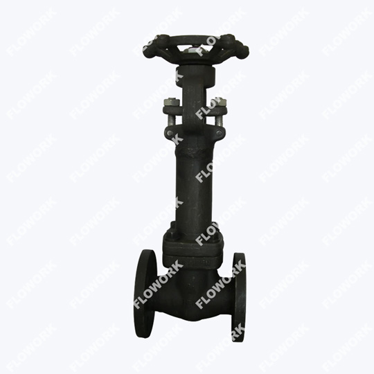
The Gas Column Principle: A cryogenic globe valve features a long extended bonnet neck that keeps the soft stem packing far away from the freezing liquid line. This design relies on a natural vapor barrier. The long neck allows cold liquid to flash into gas near the top, creating a warm insulation blanket that safeguards the upper mechanical seals.
Keep the Stem Upright: You must install these valves within 15 to 25 degrees of a vertical upright position. Tilting them too far allows cold liquid to spill up into the extension neck, drowning the vapor barrier and freezing the packing solid instantly.
BS 6364 Structural Compliance: The international standard BS 6364 enforces this exact vertical orientation alignment during field assembly. It dictates specific design and manufacturing parameters for cryogenic valve bodies to ensure that thermal contraction does not deform the seat-to-disc contact plane when sub-zero media enters the loop.
Thermal Insulation Barriers vs. Standard Utility Bronze Globe Valve Clearances
Never Insulate the Extension: While your team should insulate the cold valve body to stop process thermal losses, you must leave the top extension neck completely bare. This layout allows it to absorb room-temperature ambient air, preventing ice blocks from seizing the handwheel.
SHELL MESC SPE 77-200 Standards: For high-risk facilities, the SHELL MESC SPE 77-200 specification governs low and ultra-cryogenic operations. Shell mandates zero-leakage helium mass-spectrometer testing. Under this protocol, leaving the upper stem uninsulated is critical so technicians can inspect the live-loaded chevron packing rings for any tiny fugitive gas emissions.
Contraction Gap Planning: Leave wide physical gaps between the valve handwheel and surrounding steel columns. When liquids like LNG drop your pipeline temperature down to -196℃, the metal system will shrink up to several inches. Proper clearance stops the valve stem from binding against building beams.
Standard Bronze Clearances: On the other hand, installing a traditional utility bronze globe valve in standard ambient water or low-pressure utility lines requires only basic, low-cost clearance spaces. Your team only needs enough room to fit standard manual wrenches for quick packing gland adjustments.
BS 6364 vs. SHELL MESC SPE 77-200
Engineering Parameter
BS 6364 (Standard Cryogenic)
SHELL MESC SPE 77-200 (Severe/Ultra-Low)
Primary Testing Medium
Helium Gas or Nitrogen Gas
Highly Sensitive Helium Gas Tracking Only
Allowable Seat Leakage
Low rates based on nominal valve bore size
Near-zero bubble-tight rates (Strict ISO Class A equivalents)
Typical Target Application
Standard commercial industrial gases, air separation plants
High-risk LNG terminals, offshore gas skids, petrochemical refining
Stem Sealing Requirement
Standard low-temperature extended packing arrangements
Enhanced live-loaded chevron packing rings or bellows seals
What Problems Can Occur After a Globe Valve Installation
Even with careful work, field issues can pop up during initial system startup. Use this structural matrix to quickly identify symptoms and implement corrective actions.
System Problem
Likely Root Cause
Immediate Field Corrective Action
Passing and Internal Seat Leakage
Construction debris or welding slag trapped between the disc and the seat ring.
Open the valve fully during a high-speed line flush to sweep away the trapped grit.
Stem Binding and High Friction
Misaligned piping flanges are bending the valve body and locking the stem guides.
Loosen all flange bolts, realign the pipe hangers, and retorque using the star pattern.
Gland Weeping at Startup
Sealing packing rings relaxed and compressed during shipping and warehouse storage.
Tighten the packing gland nut evenly in small quarter-turn steps until the leakage stops.
Severe Downstream Piping Vibration
The valve was installed backwards, causing massive fluid cavitation inside the bonnet.
Shut down the system, cut or unbolt the valve, and reinstall it matching the flow arrow.
FAQs
Can you install a globe valve in any orientation?
No, it works best with the stem pointing straight up on horizontal lines to prevent uneven seat wear.
Does a globe valve always flow from under the seat?
No, high-pressure steam systems install them with flow over the disc to maintain a tighter seal during cooldowns.
How open should a socket weld globe valve be during line welding?
Open it roughly 10% to 15% to stop intense welding heat from warping or cracking the internal seals.
Why is my newly installed bronze globe valve weeping at the packing gland?
Packing fibers compress and loosen during shipping; simply tighten the gland nut a quarter-turn to reseal it.
Can I mount a globe valve upside down if space is tight?
Avoid this entirely because pipe scale will settle inside the bonnet and ruin the stem packing.
How do I know if a globe valve is installed backwards?
You will hear loud banging vibrations, feel high handwheel resistance, and see fluid passing through when closed.
Do vertical installations require special types of globe valves?
Standard valves work fine, but you must ensure the fluid travels upward against gravity through the line.
Should I remove the handwheel before welding a socket weld body?
No, but keep the valve cracked open and wrap wet cloths around the bonnet to absorb the heat.
Why does API 623 require a thicker stem diameter than traditional BS 1868 globe valves?
The thicker stem prevents mechanical bending or thread stripping when actuators slam the valve shut against severe high-pressure refinery flows.
Can I install a SHELL MESC SPE 77/200 certified valve horizontally in the field?
No. Shell specs require an upright orientation within 15 degrees to prevent liquid cryogens from reaching and freezing the stem packing.
Conclusion
Perfect globe valve installation protects your pipelines from costly fluid bypasses, broken stems, and premature packing failures. Paying close attention to flow arrows, stem angles, and welding heat preserves your component life. Contact FLOWORK today to secure high-performance, precision-machined valves that keep your facility running smoothly.