

Views:269
Share:
Why does the valve require opening torque?
What is opening torque?
Opening torque, also called operating torque, is the most important parameter for selecting a valve drive device. The size of the opening torque is also another important indicator to measure the quality of valve products. When people evaluate the quality of valves, they often describe it as light and flexible opening of the valve. In the pipeline valve standards of some advanced industrial countries, it is used as one of the assessment indicators, and it is stipulated that the opening torque of manual valves does not exceed 360N·m. If the torque exceeds this, it is necessary to consider selecting a suitable driving device (such as electric or hydraulic device). Some manufacturers print the opening torque in product samples to facilitate user selection.
Opening torque (torque) refers to the force or torque that must be exerted to open or close the valve. When closing the valve, it is necessary to form a certain sealing ratio between the opening and closing parts and the two sealing surfaces of the valve seat. At the same time, it is necessary to overcome the pressure between the valve stem and the packing, the valve stem and the thread of the nut, and the valve stem end support and the valve seat. Friction at other friction parts. Therefore, a certain closing force and closing torque must be applied. The opening and closing force and opening and closing torque required by the valve during the activation process change, with the maximum value being at the final moment of closing or the first moment of opening. When designing and manufacturing valves, efforts should be made to reduce the opening and closing force and opening and closing torque.
The opening torque can be approximated by calculation or actual measurement. For calculation formulas, please refer to relevant standards and design reference books. It can also be obtained by actual measurement using a torque wrench. For the convenience of readers, here are several types of valve opening torque characteristic curves and opening torque values. It should be noted that these chart values are empirical data under general usage conditions and are for reference only. If a matching driving device is selected, multiply the value obtained by looking up the table by a coefficient of 1.1 to 1.3 to ensure the safety and reliability of the valve product.
What is the opening torque characteristic of wedge gate valve?
The wedge gate valve opening torque characteristic curve (Figure 1-1) shows that when the valve opening is above 10%, the valve's axial force, that is, the valve's opening torque changes little. When the valve opening is less than 10%, the pressure difference between the front and rear of the gate valve increases due to fluid throttling. This pressure difference acts on the gate plate, so that the valve stem requires a larger axial force to drive the gate plate, so within this range, the change in the valve operating torque is relatively large. In the figure, the solid line represents the operating torque characteristics of the rigid gate valve; the dotted line represents the operating torque characteristics of the elastic gate valve. It can be seen from the curve that the operating torque required when the elastic gate valve is close to closing is larger than that of the rigid gate valve.

Valve opening
Figure 1-1 Opening torque characteristic curve of wedge gate valve
When the gate is closed, different situations will occur due to different sealing methods of the sealing surface. For automatic sealing gate valves (including flat gate valves), when the gate valve is closed, the sealing surface of the gate plate is exactly aligned with the sealing surface of the valve seat, which is the fully closed position of the valve. However, this position cannot be monitored under the operating conditions of the valve. Therefore, in actual use, the position where the valve is closed to the bottom dead center is regarded as the fully closed position of the gate valve. It can be seen that the fully closed position of the automatic sealing valve is determined by the position of the gate (i.e. stroke). For forced-sealing gate valves, the gate plate must exert pressure on the valve seat when the valve is closed. This pressure can ensure that the sealing surface between the gate plate and the valve seat is strictly sealed, and is the sealing force of the forcedly sealed valve. This sealing force will continue to work due to the self-locking of the valve stem thread. Obviously, in order to provide sealing force to the gate, the torque transmitted by the valve stem nut is greater than the torque during valve operation. It can be seen that for forced sealing gate valves, the fully closed position of the valve is determined according to the torque exerted on the valve stem nut.
After the valve is closed, due to changes in the medium or ambient temperature, the thermal expansion of the valve components will increase the pressure between the gate plate and the valve seat, which will be reflected on the valve stem nut, making it difficult to open the valve again. Therefore, the torque required to open the valve is greater than the torque required to close the valve. In addition, for a pair of sealing surfaces that are in contact with each other, the static friction factor between them is also larger than the kinetic friction factor. To make them move relative to each other from a static state, a larger force also needs to be applied to overcome the static friction force. Due to temperature changes, the pressure between the sealing surfaces increases, and the static friction force that needs to be overcome also increases. As a result, when the valve is opened, the torque that needs to be applied to the valve stem nut sometimes increases a lot.
The operating torque of the gate valve can be determined by referring to Table 1-1.
Table 1-1 Gate valve torque reference table
| Nominal size DN | Nominal pressure/MPa | ||||||||||
| 0.25 | 0.6 | 1.0 | 1.6 | 2.5 | 4.0 | 6.3 | 10.0 | 16.0 | 20.0 | 32.0 | |
| Torque/N · m | |||||||||||
| 50 | 25 | 25 | 50 | 50 | 50 | 100 | 100 | 200 | 200 | 200 | 200 |
| 65 | 25 | 50 | 50 | 50 | 50 | 100 | 200 | 200 | 300 | 450 | 600 |
| 80 | 50 | 50 | 50 | 80 | 100 | 200 | 200 | 300 | 450 | 600 | 900 |
| 100 | 50 | 50 | 100 | 200 | 200 | 300 | 300 | 450 | 600 | 1000 | 1200 |
| 125 | 50 | 50 | 200 | 200 | 300 | 300 | 450 | 500 | 900 | ||
| 150 | 50 | 100 | 200 | 300 | 300 | 450 | 500 | 600 | 1000 | ||
| 200 | 100 | 200 | 300 | 300 | 450 | 500 | 600 | 1000 | 1200 | 1800 | |
| 250 | 100 | 200 | 300 | 450 | 600 | 600 | 1000 | 1200 | 2500 | ||
| 300 | 200 | 300 | 450 | 500 | 600 | 900 | 1200 | 1800 | |||
| 350 | 300 | 300 | 500 | 750 | 900 | 1200 | 1800 | ||||
| 400 | 300 | 450 | 600 | 1000 | 1200 | 1800 | 2500 | ||||
| 450 | 450 | 450 | 1000 | 1200 | 1800 | 5000 | |||||
| 500 | 450 | 600 | 1200 | 1800 | 2500 | 5000 | |||||
| 600 | 500 | 900 | 1800 | 3500 | 6500 | ||||||
| 700 | 600 | 1200 | 1800 | 5000 | 8000 | ||||||
| 800 | 900 | 1200 | 2500 | 8000 | |||||||
| 900 | 1000 | 1800 | 2500 | ||||||||
| 1000 | 1200 | 1800 | 2500 | ||||||||
| 1200 | 1800 | 2500 | 3500 | ||||||||
| 1400 | 2500 | 3500 | 5000 | ||||||||
What is the opening torque characteristic of the stop valve?
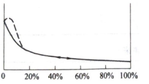
The opening torque characteristics of the stop valve (Figure 1-2) are the closing operating torque characteristics of the medium entering the valve inner cavity from the lower part of the valve. When the valve starts to close from the fully open position, as the valve disc drops, the fluid creates a pressure difference before and after the valve disc to prevent the valve disc from falling, and this resistance increases rapidly as the valve disc drops. When the valve is fully closed, the pressure difference between the front and rear of the valve disc is equal to the working pressure of the medium. At this time, the resistance is the greatest. Coupled with the forced sealing force, the operating force increases rapidly at the moment the valve closes. During the valve opening process, the thrust caused by the medium pressure or the pressure difference before and after the valve disc helps open the valve, so the shape of the valve opening characteristic curve is similar to the curve in the figure, but is located below the curve in the figure. It should be pointed out that the torque at the moment of opening the valve may exceed the torque at the time of closing the valve, because a large static friction force must be overcome at this time.
Valve opening
Figure 1-2 Stop valve opening torque characteristic curve
Figure 1-2 Stop valve opening torque characteristic curve
When the stop valve opens, when the opening height of the valve disc reaches 25% to 30% of the nominal size of the valve, the flow rate has reached the maximum, indicating that the valve has reached the fully open position, so the fully open position of the stop valve should be determined by the valve disc stroke. Sure. The situation when the stop valve is closed and when it is opened again after being tightly closed is similar to that of the forced sealing gate valve. Therefore, the closing position of the valve should be determined by increasing the operating torque to the specified value.
The opening torque of the stop valve can be determined according to Table 1-2.
Table 1-2 Stop valve torque reference table
| Nominal size DN | Nominal pressure/MPa | ||||||||||
| 0.25 | 0.6 | 1.0 | 1.6 | 2.5 | 4.0 | 6.3 | 10.0 | 16.0 | 20.0 | 32.0 | |
| force moment / N · m | |||||||||||
| 15 | 50 | 80 | 100 | ||||||||
| 20 | 80 | 100 | 200 | ||||||||
| 25 | 50 | 100 | 200 | 200 | 300 | ||||||
| 32 | 100 | 200 | 200 | 300 | 450 | ||||||
| 40 | 80 | 200 | 200 | 300 | 300 | 600 | |||||
| 50 | 50 | 80 | 100 | 200 | 300 | 300 | 450 | 900 | |||
| 65 | 50 | 80 | 100 | 200 | 300 | 300 | 450 | 600 | 1000 | ||
| 80 | 100 | 200 | 300 | 450 | 600 | 1000 | 2500 | ||||
| 100 | 100 | 200 | 300 | 450 | 600 | 1000 | 1200 | 3500 | |||
| 125 | 20 | 200 | 450 | 500 | 1000 | 1200 | 1800 | 4000 | |||
| 150 | 300 | 500 | 900 | 1200 | 1800 | ||||||
| 200 | 1000 | 1800 | |||||||||
| 225 | 500 | ||||||||||
| 250 | 500 | ||||||||||
| 300 | 500 | ||||||||||
| 350 | 500 | ||||||||||
What is the opening torque characteristic of butterfly valve?
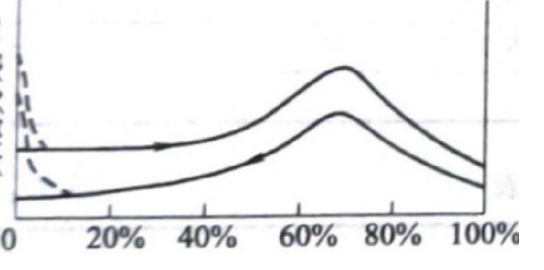
The dotted line part in the opening torque characteristic curve of the butterfly valve (Figure 1-3) is the characteristic of the sealed butterfly valve. The opening torque characteristic curve of the butterfly valve is high in the middle and low at both ends. The reason for this phenomenon is that when the butterfly valve is in the middle position, the fluid is blocked by the butterfly plate and flows around the butterfly plate, which will form a swirl flow on both sides of the butterfly plate. The butterfly plate forms a first-class water moment, which forces the butterfly plate to close. . As the butterfly plate opens or closes, the influence of the swirl flow caused by the fluid on both sides of the butterfly plate becomes smaller and smaller until the swirl flow disappears. At this time, the resistance of the butterfly plate also becomes smaller and smaller, thus forming a high middle and two sides. Characteristic curve with low end. The torque during the opening process of the valve is larger than that during the closing process. The reason is that the hydrodynamic moment caused by the fluid on the butterfly plate is always in the direction of closing the valve. The maximum opening torque of the non-sealed butterfly valve appears at the middle position, while the maximum torque of the sealed butterfly valve appears when the valve is closed. This is because a forced sealing torque is added.
The stem of a butterfly valve only performs rotational motion, and its butterfly plate and valve stem themselves do not have self-locking capabilities. In order to position the butterfly plate (stop at a designated position), one way is to attach a self-locking valve to the valve stem. With the addition of a worm gear reducer, the angular displacement can be increased to dozens of turns, while the operating torque is reduced accordingly. This can make certain operating performances of the butterfly valve (such as the total number of turns and operating torque) different from those of other valves. Close enough to facilitate the use of electric devices. For mandatory sealing butterfly valves, its closing position should be determined based on the operating torque rising to a specified value.
Valve opening
Figure 1-3 Butterfly valve opening torque characteristic curve
The operating torque of the butterfly valve can be determined by referring to Table 1-3.
Table 1-3 Butterfly valve torque reference table
| Nominal pressure | Nominal size DN | |||||||||||
| 50 | 65 | 80 | 100 | 125 | 150 | 200 | 250 | 300 | 350 | 400 | 450 | |
| force moment / N · m | ||||||||||||
| PN0.5 | 50 | 200 | ||||||||||
| PN2.5 | ||||||||||||
| PN6 | ||||||||||||
| PN10 | 50 | 50 | 100 | 100 | 200 | 200 | 450 | 600 | 900 | 1200 | 2000 | 2500 |
| Nominal pressure PN | Nominal size D N | |||||||||||
| 500 | 600 | 700 | 800 | 900 | 1000 | 1200 | 1400 | 1600 | 1800 | |||
| force moment / N · m | ||||||||||||
| PN0.5 |
| 500 | ||||||||||
| PN2.5 |
| 25000 | 30000 | |||||||||
| PN6 | 25000 | 30000 | ||||||||||
| PN10 | 3000 | 5000 | 6500 | 9000 | 15000 | 25000 |
| |||||
What is the opening torque characteristic of ball valve?
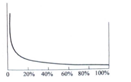
The opening torque characteristic curve (1-4) of the ball valve shows that the opening torque characteristic curves of the ball valve and the butterfly valve are similar. The reason is also due to the influence of swirling flow when the flow direction of the fluid changes in the ball. The effect of swirl flow gradually decreases as the valve is opened or closed.
Valve opening
Figure 1-4 ball valve opening torque characteristic curve
When the ball valve is fully open to fully closed, the rotation angle of the valve stem is 90°, and the ball valve must be equipped with a mechanical limit. The open and closed positions of the ball valve should be determined according to the rotation angle of the valve stem, so the ball valve is positioned according to the stroke.
The operating torque of the ball valve can be determined by referring to Table 1-4.
Table 1-4 Ball valve torque reference table
| Nominal pressure PN | Nominal size DN | |||||||||
| 50 | 65 | 80 | 100 | 125 | 150 | 200 | 250 | 300 | 350 | |
| force moment / N · m | ||||||||||
| PN16 | 25 | 50 | 100 | 150 | 250 | 500 | 1000 | 2000 | 3000 | 5000 |
| PN40 | 50 | 100 | 200 | 350 | 750 | 1200 | 3000 | 6000 | 10000 | 15000 |
| PN63 | 100 | 200 | 300 | 600 | 1200 | 2000 | 5000 | 10000 | 15000 | 20000 |