

What is the medium flow direction and sealing surface structure of the stop valve?
What is the medium flow direction of the stop valve?
Medium flow direction selection In GB/T12233 and GB/T12235, there is no provision for the medium flow direction of the stop valve. Internationally, the stop valve implements the BS1873 British standard. Article 13.6 of the standard stipulates that the valve stem and valve disc should be designed Be able to withstand the full load pressure under the closed valve disc. In other words, the stop valve medium enters from below the valve disc of the stop valve and flows out from above the valve disc. The valve stem and disc bear the full load pressure beneath the closed valve disc.
How to close and open the stop valve?
The closing or opening of the stop valve is achieved by the valve disc acting on the valve stem overcoming the dynamic pressure and static pressure on the front (or back) of the medium. Therefore, the closing and opening of the stop valve is better than that of the gate valve of the same pressure level and the same nominal size. It takes a lot of effort, so the valve stem is stressed and has a large size. Taking Z41H-6001b and DN200 as an example, the valve stem torque is 1000N·m, while the valve stem torque of J41H-6001b and DN200 stop valve is 1800N·m. The torque ratio between the two is 1:1.8. The API600 standard stipulates that the minimum valve stem diameter of Z41H-6001b and DN200 gate valves is 40.77mm. The BS1873 standard stipulates that the minimum diameter of the valve stem of J41H-600Ib and DN200 stop valve is 44.4mm. Therefore, for medium and large diameter straight-through stop valves, if the medium flow direction is from below the valve seat to above the valve seat, when closing the valve, it is necessary to "seal" the high-speed flowing medium ejected from the valve seat. Not only does the valve close The speed is slow, and the force on the valve stem is greatest at this time, which may even cause the valve stem to bend and deform. Therefore, the medium flow direction should be selected according to the diameter of the straight-through globe valve.
According to actual experience, the medium flow direction of small-diameter straight-through globe valve usually takes the form of entering the valve from the bottom of the valve disc and flowing out of the valve from the top of the valve disc. When the nominal force of the stop valve (straight-through type) is PN16~40, or Class150~300, the nominal size is ≥DN150, and the nominal pressure is ≥PN64, or ≥Class400, and the nominal size is ≥DN100, the medium flow direction is from the stop valve. The flow direction enters above the valve seat and valve disc and flows out from below the valve seat and valve disc, and the medium flow direction mark of the valve is marked on an obvious part of the valve body.
The medium of the stop valve (straight-through type) enters from the top of the valve seat and flows out from the bottom of the valve seat, which better solves the problem of large force on the valve stem when closing the stop valve. Because when closing the valve, a medium force acts on the top of the valve disc, which helps the valve close quickly and smoothly. At the same time, it greatly improves the stress condition of the stop valve stem during and after the valve closing process, which is beneficial to Operate valves safely. Taking J41H-6001b and DN200 cut-off valve as an example, if the flow direction of the medium is from the bottom of the valve seat to the top, and only the static pressure is used for analysis (the pulsation force during the flow of the medium cannot be ignored), the stop valve must be closed by The valve disc driven by the valve stem must apply an additional 31.4MPa pressure to close the valve. If the medium flows from above the valve seat to below, there is a static pressure of 1.4MPa "given" to the valve disc by the medium flow to help close the valve. . This is the reason and advantage of medium and large diameter stop valves flowing from above the valve seat to below.
What are the disadvantages of the medium flow direction of the straight-through stop valve?
There are also disadvantages in the flow direction of the medium in the straight-through stop valve from the top to the bottom of the valve seat. First, the packing area after the valve is closed
Due to the pressure of the medium behind the valve. However, the flexible graphite stainless steel wire braided packing currently used in valves can meet the working conditions.
Second, it is more laborious to open the valve. This shortcoming can be overcome if the stop valve with valve size N100~150 adopts an internal bypass structure (Figure 1-1), and the large-diameter stop valve adopts an external bypass valve structure (Figure 1-2). Therefore, it is scientific and reasonable for the medium of medium and large diameter straight-through stop valves to flow from the top to the bottom of the valve seat.
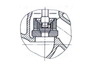
Figure 1-1 Internal bypass structure
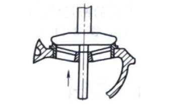
Figure 1-2 External bypass structure
What is Y-shaped globe valve?
Y-shaped stop valves (DC type) and angle stop valves have smaller flow resistance than straight-through stop valves. The diameter of Y-shaped stop valves is generally used in my country below DN200, but in European and American countries, it is also used for diameters larger than DN200. Angle type stop valve is suitable for high pressure (≥PN220) or ultra-high pressure (≥PN1000) working conditions. The diameter of this type of stop valve is generally small. When the nominal pressure is ≥PN20, the nominal size is DN15~150, but the nominal When the pressure is greater than or equal to PN1000, the nominal scale is DN3~80, and the medium flow direction is generally from the bottom of the valve disc to the top and then flows out at a 90° angle.
What is the sealing surface structure of the stop valve?
Several typical structures of sealing surfaces. The sealing surface materials of stop valves are generally divided into two types: metal seals and soft seals. Commonly used metal seal materials include 13Cr, 20Cr13, 304, 316, 304L, 316L, Monel alloy, and Stellite. Alloy, Hastelloy, 20# alloy, titanium alloy, copper alloy, aluminum alloy and cast iron, etc. Commonly used materials for soft seals include rubber, plastic, nylon, fluoroplastics and bakelite.
When sealing metal, not only the sealing stress needs to be high, but also the surrounding stress needs to be uniform to achieve the required sealing performance. Many seal designs have emerged to address these requirements. Make the valve disc and valve seat sealing surfaces flat. The advantage is that there is no friction when the contact surface is close. Therefore, the guidance of the closure is not important, and the requirements for the scratch resistance of the sealing surface material are not strict. At the same time, when the roundness of the sealing surface is deformed due to pipe stress, it will not affect the sealing performance of the sealing surface. If the medium flows from the valve seat, solid particles and sediments in the medium must be prevented from damaging the sealing surface. The flow characteristics of this sealing surface are quick-opening proportional relationships.
The sealing surface of the valve seat is right-angled, which narrows the contact surface. The sealing stress of this seal greatly increases under a certain sealing load. Since the narrow sealing surface makes it difficult for the valve disc to land correctly on the valve seat, in order to achieve the best sealing performance, the valve disc must be guided. As shown in Figure 1-3 and Figure 1-4, after the valve disc is guided and seated accurately, extremely high sealing performance can be achieved.
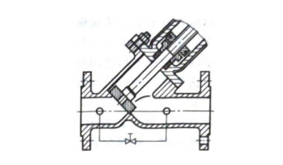
Figure 1-3 Valve seat guide structure
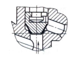
Figure 1-4 Valve guide structure
When the valve disc is guided in the valve body, the lateral thrust of the valve disc by the flowing medium is borne by the valve body instead of the valve stem. This further improves the sealing performance and sealing reliability of the packing. On the other hand, the tapered sealing surface mates under friction, so the sealing material must be resistant to scratches. Typically, this sealing surface is made of alloy steel or carbide. Narrow sealing surfaces are also more susceptible to damage from solid particles and medium sediments than wide sealing surfaces, so such seals are mainly used for dry gases without particles. Since this sealing characteristic has a linear relationship, as shown in Figure 1-5, it is suitable for use as a regulating valve.

Figure 1-5 Plug type valve disc sealing characteristics
The soft sealing surface is easily damaged by solid particles, so special attention must be paid to the filtration of the media. Soft seal structure valves are often used in steam and gas media, especially low-pressure copper valves. Soft-sealing valves require very little closing force, but they are not suitable for throttling because the surface of the medium in the throttling state is easily damaged, causing rapid damage to the valve. The soft sealing valve disc is easy to replace. As long as the sealing surface of the valve seat is not damaged, the valve performance can be restored to the original state by replacing the soft sealing part of the valve disc.