

Views:251
Share:
What are the structures of butterfly valves?
What is the centerline butterfly valve structure?
The centerline sealing butterfly valve has the entire butterfly plate and valve seat concentric within a 360° circumference, has two-way sealing performance, and the flow rate can be adjusted freely.
Most centerline butterfly valves are of the interference seal type, that is, a rubber gasket is installed on the valve seat of the valve body (Figure 1-1). If the medium is highly corrosive, PTFE can be installed, and the back of the PTFE is lined with rubber to increase the Resilience. The insert ring can be replaced, or it can be bonded to the valve body, or the insert ring can be placed on the butterfly plate. The flange surface of the rubber gasket is also a seal for the pipe flange. If a rubber gasket is added between the two flange surfaces when installing this kind of valve, it will affect the sealing performance of the rubber ring. Therefore, it is not necessary It's unnecessary.
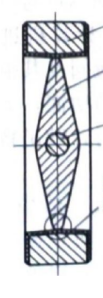
Figure 1-1 Centerline sealing butterfly valve
Since the centerline sealing butterfly valve is an interference forced sealing form, its applicable pressure is limited and is usually used under working conditions not greater than PN10. But for water supply and drainage pipes, this is enough.
What is the structure of eccentric butterfly valve?
Generally, butterfly valves have a single eccentric or double eccentric structure. The purpose of eccentricity is to make the valve seat and sealing surface separate after the butterfly plate opens to about 20°, thereby reducing friction. The double eccentric structure is designed to deviate the shaft from the center line of the sealing surface to form the first eccentricity; the shaft is slightly deviated from the center line of the pipeline to form the second eccentricity. The purpose of these two eccentricities is to reduce the friction between the valve seat and the sealing ring during the valve switching stroke. The triple eccentric metal seal butterfly valve adds an eccentric angle β on the basis of double eccentricity, which not only utilizes the original cam effect, but also completely eliminates the friction between the valve seat and the sealing ring during the 90° stroke.
First eccentricity - the shaft deviates from the center line of the sealing surface. Butterfly valves designed and manufactured according to this principle are usually called single-sided eccentric butterfly valves.
Second eccentricity - the axis is slightly deviated from the centerline of the pipeline and valve. Butterfly valves designed and manufactured according to the principles of one eccentricity and two eccentricity are usually called double eccentric butterfly valves.
Third eccentricity - As shown in Figure 1-2, the three-eccentric structure has one more eccentric angle β than the two-eccentric structure, and the sealing surface of the butterfly plate adopts an eccentric cone surface. The geometric shape makes the butterfly plate and sealing ring completely separated during the entire switching stroke of the valve. This unique eccentric combination not only utilizes the cam effect, but also completely eliminates friction, thereby achieving no friction between the butterfly plate and the valve seat sealing ring during the 90° stroke of the valve, eliminating the problem of wear and leakage.
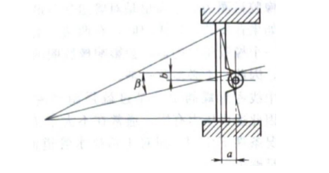
Figure 1-2 Three-eccentricity principle
The triple-eccentric metal seal butterfly valve optimizes the contact characteristics between the butterfly plate and the valve seat sealing ring. The contact angle of most butterfly valves is 3°~12.5°. This range is the locking taper range, which will produce high sealing torque and opening torque.
The contact angle of the sealing surface of the triple eccentric metal seal butterfly valve is greater than the locking taper range, which geometrically eliminates the possibility of jamming, thereby ensuring that the torque required for valve switching will not change greatly throughout the valve's service life.
What is the structure of hydraulically controlled butterfly valve?
Hydraulic control butterfly valve is currently the most advanced pipeline control equipment at home and abroad. It is mainly installed at the turbine water inlet of a hydropower station and used as a turbine water inlet valve; or it is installed at the water pump outlet of various pumping stations such as water conservancy, electric power, water supply and drainage, etc., to replace the stop valve. Return valve and gate valve functions. When working, the valve cooperates with the pipeline host, and according to the principle of hydraulic transition process, through the preset opening and closing procedures, it effectively eliminates water hammer in the pipeline, achieves reliable cutoff of the pipeline, and plays a role in protecting the safety of the pipeline system.
The hydraulically controlled butterfly valve has small flow resistance coefficient, high degree of automation, complete functions and stable performance.
Hydraulic control butterfly valves are divided into two categories according to the energy storage type of the control system: hammer type (Figure 1-3) and accumulator type (Figure 1-4). The valve mainly consists of a valve body, butterfly plate, valve shaft, sliding bearing, It is composed of sealing components and other parts.
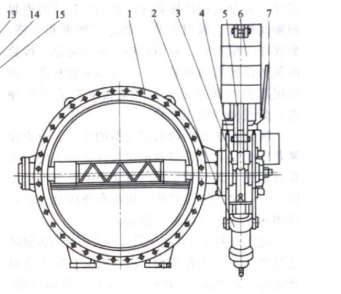
Figure 1-3 Heavy hammer hydraulically controlled slow-closing check butterfly valve
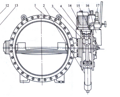
Figure 1-4 Accumulator-type hydraulically controlled slow-closing check butterfly valve
The heavy hammer valve body adopts horizontal structure, and the valve shaft adopts half-shaft structure. The accumulator type generally adopts horizontal arrangement; it can also adopt vertical arrangement according to user requirements.
The transmission mechanism is mainly composed of hydraulic cylinders, rocker arms, support plates (weight type also has weights, levers, locking cylinders, etc.) and other connecting and transmission parts. It is the main actuator for opening and closing valves with hydraulic power.
The transmission hydraulic cylinder is equipped with a fast closing time regulating valve, a slow closing time regulating valve and a fast and slow closing angle regulating valve. The hydraulic station includes oil pump unit, manual pump, accumulator, solenoid valve, relief valve, flow control valve, stop valve, hydraulic integrated block, fuel tank and other components.
In the hammer-type automatic pressure-maintaining system, the accumulator is used to compensate for the system pressure. In the weight-type automatic pressure-maintaining locking system, the accumulator is used to compensate for the system pressure and to unlock the locking cylinder. In the accumulator system, the two accumulators serve as backup for each other and provide the main power source for the valve opening and closing.
The flow control valve is used to adjust the opening and closing time of the valve. Manual pumps are used for system debugging and valve opening and closing under special working conditions. The control characteristics of the electromagnetic reversing valve in the hydraulic system are generally forward-acting models, that is, the butterfly valve opens when power is supplied to the solenoid valve, and closes when power is lost; conversely, it is a reaction type, that is, the butterfly valve opens when power is lost to the solenoid valve, and closes when power is lost. Conventionally matched electromagnetic reversing valves are of the positive-acting type. If the reverse-acting type is used, please indicate when ordering.
The hydraulic system and the valve body can be installed integrally or separately. Unless otherwise specified by the user, it is an integral installation. When the accumulator is installed vertically, it is installed in a split type.
What are the characteristics of CNC butterfly valve?
a. It can replace the functions of the original gate valve and check valve at the outlet of the water pump, and the mechanical, electrical and hydraulic systems are integrated into a whole, reducing the floor space and infrastructure investment.
b. The electro-hydraulic control function is complete and can be debugged and controlled on-site as an independent system without additional configuration; it can also be used as an equipment unit of the distributed control system (DCS), centralized by the central computer through the I/O channel Management, and realizes linkage operation with water pumps, turbines, bypass valves and other pipeline equipment; and is equipped with a manual function, which can also realize manual opening and closing of valves when there is no power source, meeting the valve debugging and control requirements under special working conditions.
c. Good controllability, large adjustment range and strong adaptability. The electro-hydraulic control system is equipped with multiple adjustment points, and the opening and closing procedures can be set according to different pipeline control requirements to ensure that when the valve opening and closing conditions are met, the valve can automatically open and divide according to the preset time and angle. Slow two-stage shutdown. It can also realize non-electrical valve closing, effectively eliminate destructive water hammer, prevent the occurrence of water pump and turbine unit runaway accidents, reduce pressure fluctuations in the pipe network system, and ensure safe and reliable operation of equipment.
d. The main valve seal pair is a triple eccentric metal seal or double eccentric rubber seal structure, which is easy to open and close and has reliable sealing. It also has an additional increased eccentricity, so that the valve has good self-closing and self-sealing performance. The medium and small diameter butterfly plates are designed as streamlined flat plates, and the large diameter butterfly plates are designed as double flat plate truss structures, with small displacement and smooth water flow. The valve flow resistance coefficient is only 0. 1 to 0.6, which is much smaller than the flow resistance of the check valve. Coefficient (1.7~2.6), the energy saving effect is obvious.