

Views:265
Share:
What are the structural types and uses of stop valves?
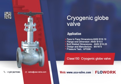
A valve in which the valve disc, driven by the valve stem, moves up and down along the axis of the valve seat sealing surface to achieve the purpose of opening and closing, is called a globe valve.
What is the use of stop valve?
The stop valve is a type of cut-off valve, used to cut off or connect the medium in the pipeline. Small diameter stop valves mostly use external thread connection or ferrule connection or welding, while larger diameter stop valves use flange connection or welding. Stop valves mostly use handwheel or gear transmission. In situations where automatic operation is required, electric, pneumatic, hydraulic and other transmissions can also be used. The fluid resistance of the stop valve is very large, and the opening and closing torque is also large, which affects its application in large-diameter situations. In order to expand the application range of the stop valve, a bypass valve can be installed to balance the pressure in the pipelines on both sides of the main valve opening and closing parts. The high-pressure balanced stop valve has a small hole in the plunger (Figure 1-1), so that The upper and lower pressures are balanced, the opening and closing torque is reduced, and it has the same function as the bypass valve. It is suitable for occasions with large high-pressure caliber. The performance parameters of the currently produced stop valves range from nominal pressure PN6 to 320, nominal size DN3 to 300, and operating temperature t≤550°C.

Figure 1-1 J47Y-160/320 high pressure balanced stop valve
What are the types of stop valves?
According to the structural form, stop valves can be divided into the following types: straight flow channel, straight flow channel, unbalanced valve disc, Z-shaped flow channel, angle flow channel, three-way flow channel, straight flow channel, upper threaded valve stem, cut-off valve Valve, disc balanced type, angle flow channel, lower threaded valve stem, upper threaded valve stem, inclined rod type - straight-through type, needle disc globe valve, lower threaded valve stem.
What are the characteristics of the stop valve?
① Advantages
a. The structure is simpler than the gate valve, and it is easier to manufacture and maintain.
b. The sealing surface is not easy to wear and scratch, and has good sealing performance. There is no relative sliding between the valve disc and the valve body sealing surface when opening and closing, so the wear and scratches are not serious. The sealing performance is good and the service life is long.
c. When opening and closing, the valve disc stroke is small, so the height of the stop valve is smaller than that of the gate valve, but the structural length is longer than that of the gate valve.
② Disadvantages
a. The opening and closing torque is large, the opening and closing is more laborious, and the opening and closing time is longer.
b. The fluid resistance is large, because the medium channel in the valve body is tortuous, the fluid resistance is large, and the power consumption is large.
c. The valve disc is often eroded when fully open.
What is the structure of the stop valve?
The stop valve is mainly composed of valve body, valve cover, valve stem, valve stem nut, valve disc, valve seat, stuffing box, sealing packing, packing gland and transmission device.
① Valve body and valve cover The globe valve body and valve cover can be cast or forged. The cast body and valve cover are used for large diameter valves, generally ≥DN50. Low-pressure valves with small diameters are also cast. Forged valve bodies and valve covers are generally used for high-temperature and high-pressure valves ≤DN50, as shown in Figure 1-1. Globe valves can also adopt structural forms such as forge welding, cast welding, and tube-sheet welding. The valve body and bonnet are generally connected by threads or flanges. In high-pressure stop valves, the valve body and bonnet are connected. Currently, most power stations use a centerless flange pressure sealing structure. The sealing ring uses formed packing, and the wedge is pressed by the medium pressure. The sealing ring is used to achieve sealing. The higher the medium pressure, the better the sealing performance, see Figure 1-2. The flow path of the globe valve body can be divided into straight-through type, right-angle type and direct-flow type.
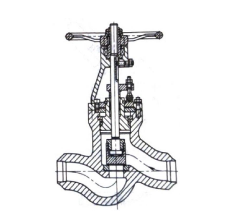
Figure 1-2 J61Y-P54100V welded connection self-sealing high temperature and high pressure stop valve
a. Straight-through globe valve: There is a partition between the inlet and outlet channels of the cast straight-through valve body, as shown in Figure 1-3, so the fluid resistance is very large.
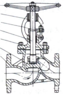
Figure 1-3 J41H straight-through globe valve
b. Angle globe valve: The center line of the inlet and outlet channels of the angle valve body is at a right angle, and the medium flow direction will also become a 90° angle. The angle valve body is mostly forged and is suitable for high pressure and small diameter stop valves, see Figure 1-4.
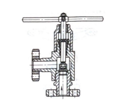
Figure 1-4 J44Y high pressure angle stop valve
c. DC stop valve: DC valve body is used in inclined rod stop valve. The axis of the valve stem and the axis of the outlet end of the valve body channel form a certain acute angle, usually 45°~60°. The medium basically flows in a straight line. Therefore, it is called a DC stop valve, and its resistance loss is smaller than the previous two (Figure 1-5).
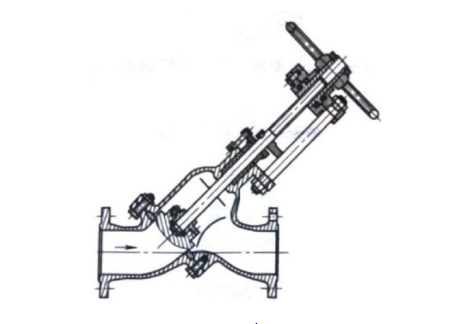
Figure 1-5 J45H type DC stop valve
② The valve stem of the globe valve generally rotates and lifts, and the handwheel is fixed on the upper end of the valve stem; some also drive the valve stem nut to rotate through a transmission device (handwheel, gear transmission, electric, etc.), so that the valve stem has a valve disc. Do lifting movements to achieve the purpose of opening and closing. According to the position of the thread on the valve stem, it is divided into upper threaded valve stem and lower threaded valve stem.
a. Upper threaded valve stem: The thread is located on the upper half of the valve stem. It does not come into contact with the medium, so it is not corroded by the medium and is easy to lubricate; it is suitable for stop valves with larger diameters, high temperatures, high pressures or corrosive media.
b. Lower threaded valve stem: The thread is located on the lower half of the valve stem, see Figure 1-6. The thread is located in the valve body cavity and is in contact with the medium. It is easily corroded by the medium and cannot be lubricated. Stop valve suitable for small diameter, lower temperature and non-corrosive media.

Figure 1-6 J11T threaded concealed stem stop valve
③ Valve disc It is the opening and closing part of the stop valve and the key pressure control part of the stop valve. There is a sealing surface on the valve disc and the valve seat together to form a sealing pair to connect or cut off the medium. Usually the valve disc is disc-shaped, with flat and conical sealing forms. The functions of other parts are the same as those of the gate valve and will not be described again.