

1、You are in restricted area and need password. Please Contact us to obtain documents.
2、PasswordIf you have any questions about quotation or cooperation, please feel free to send us inquiry. Inquiry us
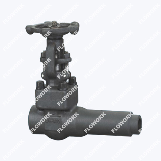
| Size: | 1/2"-2" |
| Pressure: | 150LB-2500LB |
| Body Material: | A105, F304, F304L, F316, F316L, LF1, LF2, LF3, LF9, F51, F53, F11, F22, etc. |
| Seal Material: | STELLITE, 13Cr, SS304, SS316, etc. |
| Connection Type: | Butt welded |
| Operation: | Handwheel, gear operated, pneumatic, motorized |
| Face to Face Dimension: | ASME B16.10 |
| Flange End Dimension: | ASME B16.5 |
| Butt Welded Dimension: | ASME B16.25 |
| Design and Manufacture: | API 602 |
| Test Standard: | API 598, API624,API 6FA, ISO 15848-1-2 |
Approved by design standard API 602
Available with bolted bonnet, welded bonnet and pressure seal bonnet
OS&Y, rising stem, expanded seat rings, solid wedge
Available with socket welded/ butt welded/ threaded/ flange ends
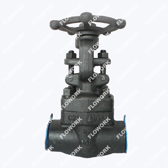
Renewable seat and integral seat are both adoptable
Available to equip nipple extension on both ends
With the advantage of low fluid resistance; flow direction of the medium is not restricted
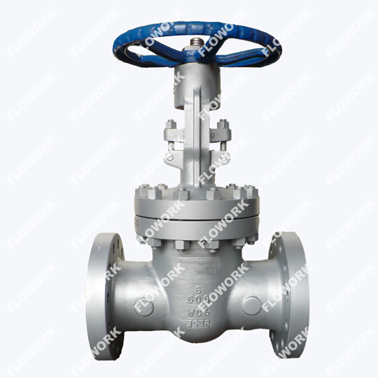
Sluice valves and gate valves are both types of valves commonly used in plumbing and industrial applications, but they differ in their design, construction, and application. Here are the key differences between sluice valves and gate valves:
Design: Sluice valves are designed with a rising stem and a rectangular or circular gate that slides vertically to control the flow of fluids, while gate valves have a gate or wedge-shaped disk that moves up and down to open or close the valve.
Construction: Sluice valves have a solid body and a non-removable gate that is machined into the valve body, while gate valves have a removable gate that is attached to the stem. api 6d ball valve
Application: Sluice valves are commonly used in applications where a full bore and low pressure drop are required, such as in water treatment plants, sewage treatment plants, and pipeline systems. Gate valves, on the other hand, are used in applications where a tight seal and high-pressure capacity are required, such as in oil and gas pipelines, steam lines, and fire protection systems.
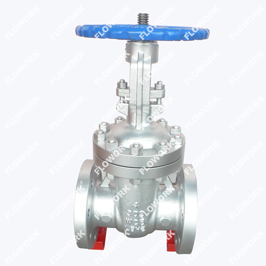
Maintenance: Sluice valves are easier to maintain and repair than gate valves, as they have fewer parts and the gate is fixed in place, while gate valves require more frequent maintenance to ensure the gate moves freely and does not become stuck in the valve body. forged ball valve
In summary, sluice valves are designed for low pressure and full bore applications, while gate valves are designed for high-pressure applications where a tight seal is required. Sluice valves are easier to maintain and repair, while gate valves require more maintenance but offer greater pressure capacity and sealing ability.
Adjusting the packing of a gate valve involves tightening or loosening the packing gland to ensure that the valve stem is properly sealed and lubricated. Here's how you can adjust the packing of a gate valve:
Turn off the fluid flow: Before adjusting the packing of a gate valve, turn off the fluid flow and isolate the valve from the system.
Remove the packing gland bolts: Using a wrench or pliers, loosen and remove the packing gland bolts located on top of the valve body.
Loosen the packing nut: Using a wrench, loosen the packing nut that surrounds the valve stem. Do not completely remove the nut. carbon steel gate valves
Adjust the packing material: Use a packing material suitable for the type of fluid and temperature of the system, and add or remove packing material to achieve the desired tightness around the valve stem.
Tighten the packing nut: Use a wrench to tighten the packing nut until it is snug against the packing material, but be careful not to over-tighten it.
Replace the packing gland bolts: Replace the packing gland bolts and tighten them evenly in a criss-cross pattern to ensure an even and tight seal.
Turn on the fluid flow: Turn on the fluid flow and check for any leaks around the valve stem. If there are any leaks, adjust the packing again as needed.
Note: It is important to follow the manufacturer's instructions and safety guidelines when adjusting the packing of a gate valve. If you are unsure about how to proceed, consult a professional valve technician or engineer for assistance.
The pressure drop across a gate valve can be calculated using the following equation:
ΔP = K * ρ * V^2 / 2
Where:
ΔP = pressure drop across the valve (in Pascals or PSI)
K = valve coefficient or resistance coefficient
ρ = fluid density (in kg/m³ or lb/ft³)
V = fluid velocity (in m/s or ft/s)
To calculate the valve coefficient (K), you need to know the valve size, type, and design. The manufacturer's data sheet for the valve should provide the valve coefficient.
Once you have the valve coefficient (K), the fluid density (ρ), and the fluid velocity (V), you can calculate the pressure drop (ΔP) across the gate valve using the above equation. high temperature gate valves
Here is an example:
Suppose you have a gate valve with a coefficient of 0.85, handling water with a density of 1000 kg/m³ and a flow rate of 10 m³/h. The inside diameter of the valve is 50 mm. What is the pressure drop across the valve?
Convert flow rate to velocity:
v = Q / A, where
Q = flow rate = 10 m³/h = 0.0028 m³/s
A = cross-sectional area = π*(d/2)^2 = π*(50/2)^2 = 1963.5 mm²
v = 0.0028 m³/s / 0.0019635 m² = 1.42 m/s
Calculate pressure drop:
ΔP = K * ρ * V^2 / 2, where
K = 0.85 (from valve manufacturer's data)
ρ = 1000 kg/m³ (water density)
V = 1.42 m/s (fluid velocity)
ΔP = 0.85 * 1000 kg/m³ * (1.42 m/s)^2 / 2 = 855 Pa
Therefore, the pressure drop across the gate valve in this example is 855 Pa (or approximately 0.124 PSI).
The term "wog" on a gate valve typically refers to the valve's pressure rating. Specifically, it stands for "Water, Oil, and Gas," which are the three most common fluids that the valve is designed to handle. Gate valves marked with "wog" typically have a pressure rating that is suitable for use with water, oil, and gas. This information is usually stamped or engraved on the valve body to indicate the maximum pressure that the valve can withstand when used with these fluids.
A class 150 gate valve is a type of gate valve that is designed and manufactured to withstand a maximum pressure of 150 pounds per square inch (PSI) at ambient temperatures. The class 150 rating is a pressure rating defined by the American Society of Mechanical Engineers (ASME) and is commonly used in piping systems for applications such as water, oil, and gas, duplex stainless steel ball valve.
Gate valves with a class 150 rating typically have a flanged or threaded end connection, and are made of materials such as cast iron, ductile iron, carbon steel, stainless steel, or bronze. These valves are often used in low-pressure applications where the flow of fluid needs to be completely shut off or regulated, such as in pipelines, tanks, and other fluid-handling systems.
It is important to note that the class rating of a gate valve should be carefully selected based on the specific requirements of the application, taking into account factors such as the type of fluid, temperature, pressure, and flow rate, to ensure the safe and efficient operation of the system, fugitive emission gate valve.
Send us a message if you have any questions or request a quote.

A reply from our experts within 24 hours
The latest detailed product catalugue
One-stop service for your project